Having issues troubleshooting low voltage on a Westerbeke 5.0 BCD generator.
I removed the genset shortly after purchasing my boat a few years back, as far as I am aware it was operating fine but I never had a need for it so out it came.
I have since sent the unit out for servicing as the voltage output was only 160 - 170 VAC at 50 Hz instead of 220 - 240 VAC.
First contractor checked that it was wired as per the Westerbeke manual eg. on 50 Hz connection and output of main stator windings connected to AC terminal block.
Output voltage was till low but could be varied upto 190 VAC by changing connections on AC terminal and increasing RPM.
Second contractor found that stator had been rewound previously and that seemed the problem, he did confirm that he had read the manual and understood what the resistance should be however that seems doubtful as the stator was rewound with the same low voltage result.
I insisted he calculate what the windings should be and stator was rewound again with the same result.
The unit was sent out because I did not have the time to troubleshoot it so this is the stage where I went through the manual.
Guessed that if the primary windings were not putting out enough voltage then there was a problem at the rotor windings.
Requested the second contractor to desolder and check that the two diodes on stator were functioning correctly. One of the diodes was fine, infinite resistance one way and no resistance the other way. Second diode is questionable as it has infinite resistance one way and slight resistance the other way, no numbers just observation from a video sent to me.
I will check these diodes myself next month to confirm their function as well as the dual capacitors for exciting the windings.
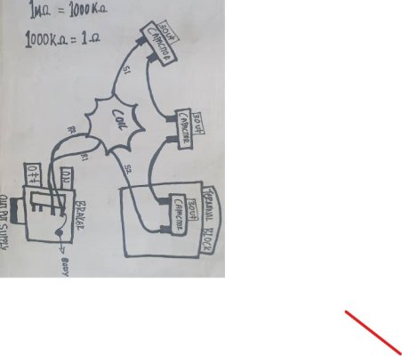
Strangely, there is a third capacitor in the junction box and I cannot figure out why it is connected to the dual capacitors, refer to attached sketch.
There is no ID tag on the alternator and no wiring diagram on plate at back of stator to confirm if the wiring is correct so all I have to go off are the technical manuals.
I requested a long line wiring diagram from the local Westerbeke agent and the response from Westerbeke was that they could not help as the unit had been rewound.
So, does anyone have any insights into what could be going on with the wiring or, ideally, a contact who could help me with a long line wiring diagram?
I removed the genset shortly after purchasing my boat a few years back, as far as I am aware it was operating fine but I never had a need for it so out it came.
I have since sent the unit out for servicing as the voltage output was only 160 - 170 VAC at 50 Hz instead of 220 - 240 VAC.
First contractor checked that it was wired as per the Westerbeke manual eg. on 50 Hz connection and output of main stator windings connected to AC terminal block.
Output voltage was till low but could be varied upto 190 VAC by changing connections on AC terminal and increasing RPM.
Second contractor found that stator had been rewound previously and that seemed the problem, he did confirm that he had read the manual and understood what the resistance should be however that seems doubtful as the stator was rewound with the same low voltage result.
I insisted he calculate what the windings should be and stator was rewound again with the same result.
The unit was sent out because I did not have the time to troubleshoot it so this is the stage where I went through the manual.
Guessed that if the primary windings were not putting out enough voltage then there was a problem at the rotor windings.
Requested the second contractor to desolder and check that the two diodes on stator were functioning correctly. One of the diodes was fine, infinite resistance one way and no resistance the other way. Second diode is questionable as it has infinite resistance one way and slight resistance the other way, no numbers just observation from a video sent to me.
I will check these diodes myself next month to confirm their function as well as the dual capacitors for exciting the windings.
Strangely, there is a third capacitor in the junction box and I cannot figure out why it is connected to the dual capacitors, refer to attached sketch.
There is no ID tag on the alternator and no wiring diagram on plate at back of stator to confirm if the wiring is correct so all I have to go off are the technical manuals.
I requested a long line wiring diagram from the local Westerbeke agent and the response from Westerbeke was that they could not help as the unit had been rewound.
So, does anyone have any insights into what could be going on with the wiring or, ideally, a contact who could help me with a long line wiring diagram?