JDCAVE
Guru
- Joined
- Apr 3, 2011
- Messages
- 3,010
- Location
- Canada
- Vessel Name
- Phoenix Hunter
- Vessel Make
- Kadey Krogen 42 (1985)
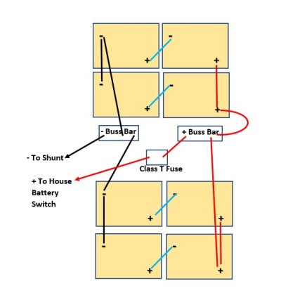
As mentioned in an earlier thread, I have replaced my 10 X T-105's Golf Cart bank with 8 X T-105's. The previous bank was not "as balanced" in its charging design as preferred, so I have designed a new arrangement as shown in the schematic. In addition, I would like to move the overcurrent protection (Class-T) closer to the battery terminal.
Some points:
1) the cables from the battery boxes to the buss bars will be of equal length.
2) the positive cabling from the battery boxes to the buss bars will be in loom.
3) total length of cable from the battery box to the Class T fuse will be 3'.
4) all cabling after the fuse and buss bars will be as before.
5) as before, this is a 12 VDC bank.
This is proposed at this time. No work has been done. The Class T Fuse is currently after the battery switch (some considerable distance from the battery boxes) and it is "probably" not "approved" under ABYC guidelines.
I should say that I got 9 seasons out of my last bank of T-105's. After 2 weeks at rest, the individual batteries were at 6.45 volts and within 0.02 of a volt of one another. I hope these last accordingly.
Any comments or suggestions most graciously accepted.
Jim
Attachments
Last edited:


