So it sounds like you removed the bar(s) that buss all the breakers together and have, for a lack of a better way to describe it, a remote buss for the breakers? Y'all got any pics of this type of install? I am not at all uncomfortable doing it myself, but it would require a great deal of dis-assembly and time. My breaker panel is in a pretty awkward place.
I dont have photos, but here it goes.
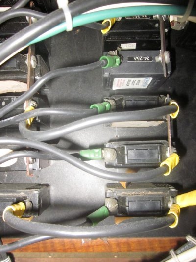
Most AC panels are made up of columns.
Each column is made up of breakers.
The breakers are connected together on the power feed side using tin plated copper bars, with holes drilled in them for attachment to the breakers.
The best method is to separate the AC panel into two panels. One being fed from shore power, and one being fed from the inverter. This is done by removing the copper bar, and cutting it into two sections.
This is the best method because it logically separates the inverter loads from the shore power loads. This is the method I've used several times. The challenge with this method, is that you have to re-arrange the load wires to put all the inverter loads in one physical section. This can make for a messy looking panel, and possibly require splicing wires, something I almost never do. As an electrical professional I seriously dislike butt splices. Installing a terminal strip is a much better solution.
Another method, which I've also used is to pick the breakers that you want to have on inverter power, and remove the buss bar from that breaker only. You then jumper around the removed section using a 10AWG wire (on a 30 amp panel). Then you wire the breakers that you freed up to the inverter output through a buss bar. Then you mark the breakers that are on inverter power. A colored tye wrap through a hole in the handle works great
I've done it both ways, and prefer the first method, although the second method works just fine as well.
 More than half the fun of this whole experience is doing things and learning to do things myself. Yes, I will make some mistakes and will likely do a few dangerous things along the way (and perhaps take and give some bad advice), but that's a risk I am willing to take to be the best boater I can be. Paying someone THAT much money not only extinguishes that fun... it puts a beat-down on my bank account in the process.