BDofMSP
Guru
- Joined
- Sep 5, 2013
- Messages
- 933
- Location
- USA
- Vessel Name
- Gopher Broke
- Vessel Make
- Silverton 410 Sport Bridge
I’ve been thinking about adding an inverter as a future enhancement. There are a lot of different models, with a range of options, and I get confused about the installation requirements. The “rest of the internet” is not a lot of help – I get a ton of conflicting information and much of it is not marine-based anyway. So I seek to better understand.
Before I even start this, let me say that I’ll definitely work with a qualified marine electrician to do the work, so don’t worry that I’m going to kill myself or burn down the boat. But I like to understand how everything works, and frankly I have gotten contradictory information from “qualified marine electricians”, which confuses me even more.
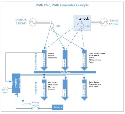
Background about the boat, it has a single 50 amp 120/240 AC service with no 240 circuits on board. Each line feeds a separate 120 volt half of the panel. There is also a generator that also powers each line, and a sliding interlock to manage the switches and isolate the sources. Very traditional.
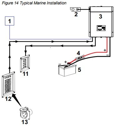
I’d like to start with the most simple example with the disclaimer that I’m really trying to avoid rebuilding my entire electrical panel as much as possible. In this simple example we’ll act as though my boat has no generator, and I’m just adding the inverter. Pretend also that I am happy only powering the loads on one half of the panel with the inverter. The other line would remain cold when I’m not on shore power. I’ve attached a diagram of that solution, and I’d appreciate feedback. Essentially it shows me adding the inverter where the Gen currently is wired, but since it’s only 120 it is only powering Line 1 circuits. The manual interlock protects against simultaneously powering with both sources.
In the 2nd figure I extend the solution to match my current situation. I replace the sliding interlock with a rotary selector switch such as a Blue Sea 1488 (120/240V AC Rotary 65A OFF + 3 Sources), also pictured in that figure. This allows me to keep the gen, hence powering both lines offshore if needed, but enabling my simple needs to run off the inverter most of the time. The inverter would be “Shore 2”.
Note: In NEITHER of these situations is the inverter powered by AC with a pass through or a transfer switch. Moreover, this is simply an inverter, not a charger. I’m trying to keep this example simple for now.
So, details of the inverter installation aside (gauge of the wire, chassis ground, etc.) and ignoring perhaps not using the ideal symbols in every case, are both of these solutions safe and compliant with ABYC? Comments appreciated.
Thanks
BD
Before I even start this, let me say that I’ll definitely work with a qualified marine electrician to do the work, so don’t worry that I’m going to kill myself or burn down the boat. But I like to understand how everything works, and frankly I have gotten contradictory information from “qualified marine electricians”, which confuses me even more.
Background about the boat, it has a single 50 amp 120/240 AC service with no 240 circuits on board. Each line feeds a separate 120 volt half of the panel. There is also a generator that also powers each line, and a sliding interlock to manage the switches and isolate the sources. Very traditional.
I’d like to start with the most simple example with the disclaimer that I’m really trying to avoid rebuilding my entire electrical panel as much as possible. In this simple example we’ll act as though my boat has no generator, and I’m just adding the inverter. Pretend also that I am happy only powering the loads on one half of the panel with the inverter. The other line would remain cold when I’m not on shore power. I’ve attached a diagram of that solution, and I’d appreciate feedback. Essentially it shows me adding the inverter where the Gen currently is wired, but since it’s only 120 it is only powering Line 1 circuits. The manual interlock protects against simultaneously powering with both sources.
In the 2nd figure I extend the solution to match my current situation. I replace the sliding interlock with a rotary selector switch such as a Blue Sea 1488 (120/240V AC Rotary 65A OFF + 3 Sources), also pictured in that figure. This allows me to keep the gen, hence powering both lines offshore if needed, but enabling my simple needs to run off the inverter most of the time. The inverter would be “Shore 2”.
Note: In NEITHER of these situations is the inverter powered by AC with a pass through or a transfer switch. Moreover, this is simply an inverter, not a charger. I’m trying to keep this example simple for now.
So, details of the inverter installation aside (gauge of the wire, chassis ground, etc.) and ignoring perhaps not using the ideal symbols in every case, are both of these solutions safe and compliant with ABYC? Comments appreciated.
Thanks
BD