SteveK
Guru
- Joined
- Jul 5, 2019
- Messages
- 5,861
- Location
- Gulf Islands, BC Canada
- Vessel Name
- Sea Sanctuary
- Vessel Make
- Bayliner 4588
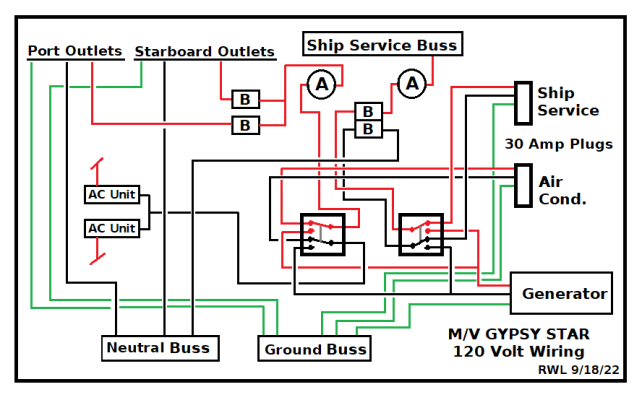
The original schematic paths make sense except the neutral from generator.
The gen neutral goes to the left (AC) switch but it also should go to the right (service) switch like the hot (red wire) in the terminal on switch from the neutral buss at far right. There should not be a wire from neutral buss to (service) switch.
As you said the ground and neutral are connected at the generator but the neutral from the generator is only going to the AC and nothing to the receptacles because of that loop I mentioned before if it is wired as the schematic shows.
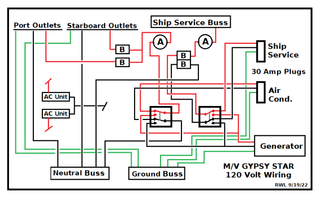
ETA: your post 19 shows neutral going to both switches.
The gen neutral goes to the left (AC) switch but it also should go to the right (service) switch like the hot (red wire) in the terminal on switch from the neutral buss at far right. There should not be a wire from neutral buss to (service) switch.
As you said the ground and neutral are connected at the generator but the neutral from the generator is only going to the AC and nothing to the receptacles because of that loop I mentioned before if it is wired as the schematic shows.
ETA: your post 19 shows neutral going to both switches.
Last edited: