Electrical Mystery (120 volt)

The friendliest place on the web for anyone who enjoys boating.
If you have answers, please help by responding to the unanswered posts.

Roger Long

Senior Member
Joined
Jul 14, 2015
Messages
451
Location
Albany
Vessel Name
Gypsy Star
Vessel Make
Gulf Star 43
Resolved but, if you like a mystery....

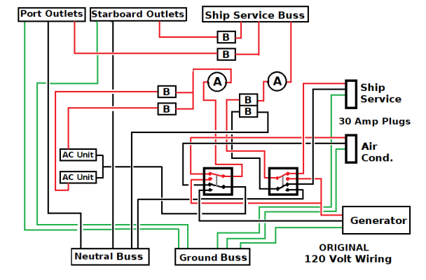
Our 1975 vintage Cruiseair reverse cycle AC system reached its “Use By” date during the August heat wave. Since we survived, I figure we can kick that can down the road but we need the heat for going south. We prefer to use portable ceramic heaters anyway since they are quieter and we can put them where they are most needed. Our two Cruiseair units were on a separate AC bus so I decided to disconnect them and send the output from the two breakers to the two separate circuits for the port and starboard outlets (after disconnecting them from their breakers of course)so we can run an additional heater and also cook and make hot water without needing to shut the heaters off.

Quick and simple job and I used one of those three LED testers to be sure I hadn’t slipped up somewhere tracing the wire bundles with my fingers. All good so I went to have lunch. I returned and finished re-bundleing the wires with cable ties and replacing the access panel and helm wheel. I then noticed that a rechargeable flashlight I had plugged in was not charging. I stuck the tester in and, yikes, it showed that hot and ground were reversed. I checked directly at the pedestal and boat end of the power cord and got the proper indication both places. Switched everything on and off, rechecked all the connections, no joy. Every outlet in the boat showed the same thing.

I decided to try it on the generator to see what I could learn. Disconnected the shorepower, fired up the Westerbeke, and checked the outlets. Everything was good, two LED’s showing properly.

I then turned off the generator and went back to shore power. Every outlet good. Switched things on and off and could not recreate the problem. The boat is very simple, pretty much exactly as she came out of the yard in 1975. No isolation transformers, inverters, or anything fancy.

Anyone have any idea what could have been going on here?

I did notice that the shore power voltage was 138. I told the marina and they said the boost transformers they use because of the long docks haven’t been readjusted yet now that they don’t have a lot of boats running air conditioning. I leave the boat unplugged anyway so I’m not concerned about that.
 
It sounds like perhaps you have also reached end of life on your flux capacitor. West Marine usually maintains a good stock.
 
Don't use Westerbeke generators :ermm::ermm:
 
It sounds like perhaps you have also reached end of life on your flux capacitor. West Marine usually maintains a good stock.


I've searched the whole system for one of these and it's not there. Boat is 1975 so none could have been installed until 1985. West Marine is back ordered until 2015.
 

Attachments

  • index.jpg
    index.jpg
    7.3 KB · Views: 271
Resolved but, if you like a mystery....

When you say it's resolved, did you find the cause and rectify it, or it's just back to the way it should be? One is safe, the other may repeat with a bad result.

I'm guessing there are no GFI outlets on the boat or GFI breakers at the power pedestal?

Ted
 
When you say it's resolved, did you find the cause and rectify it, or it's just back to the way it should be? One is safe, the other may repeat with a bad result.


No cause found. That's primarily why I posted. There are GFI outlets in the galley and head and they did not trip. I've used the 3 LED testers for years and never had a false reading. I usually keep one plugged in as a pilot light and a quick check for marina wiring problems when we plug in. I have experienced those.


The marina wiring does not have the new GFI arrangements causing old boat so many problems. I'll keep the LED tester plugged in and keep an eye on it.


After sleeping on it: The boat has two 30 amp shore power connectors, one for ship's service and one for air conditioning. There are also two transfer switches. Absent the generator, the two systems are isolated except for the ground. The generator however feeds both so connects them through it's wiring. I'm careful not to turn either transfer switch to "Ship's Power" when shore power is connected but maybe I slipped up while working under the panel. I'll have to go back and see if there is a switch setting that will duplicate the problem.
 
Was anything else plugged into an outlet with a 3 pin plug (grounded) when the positive and ground were reversed? Does the flashlight charger have a grounded plug? Did you disconnect all the wires to the air conditioner circuit or just the positive wire? When you moved the outlets to the air conditioning shore power circuit, did you move the neutral wires in addition to the positive?

Did you have a couple of beers with lunch? :rolleyes:

Ted
 
Was anything else plugged into an outlet with a 3 pin plug (grounded) when the positive and ground were reversed?


No, just the USB flashlight with 2 prong USB charger.


Did you disconnect all the wires to the air conditioner circuit or just the positive wire?
No. It's not a true separate bus. There is only one negative bus bar. I think it's an artifact of 50 amp shore power not being common in 1975 so two 30 amp cords could be connected.


When you moved the outlets to the air conditioning shore power circuit, did you move the neutral wires in addition to the positive?
No place to move them to.


Did you have a couple of beers with lunch?
No beer when working with 120 volts.
 
I see one issue. If you have a 50A 120/240 setup or twin 30 amp inlets and only have a single neutral bus for 120v loads, you MUST separate the neutral bus into 2 (1 for he loads on each inlet or 50A leg). If you don't do this, you can NEVER plug the boat into 2 separate 30 amp shore outlets with GFCI breakers, as it will trip the breakers as soon as you turn on any load.

Wiring multiple inlets with a shared neutral bus is a lazy, half-ass method used by some boat builders on older boats. In the pre-GFCI era, they could get away with it, but it was always wrong.
 
No, just the USB flashlight with 2 prong USB charger.


No. It's not a true separate bus. There is only one negative bus bar. I think it's an artifact of 50 amp shore power not being common in 1975 so two 30 amp cords could be connected.


No place to move them to.


No beer when working with 120 volts.

Ok, this is me thinking allowed:

For your plug in circuit tester to show an LED indicating that the ground is hot, I would assume that the LED is between the ground and the neutral wire. So I would be looking for something bleeding milliamps between the positive and the ground (like an older style galvanic isolator with an LED indicator light.

Btw, I know this is picky, but for the sake of clarity, there is no "negative" in AC wiring. The white wire is a neutral. Negative is only in DC wiring.

Ted
 
If you don't do this, you can NEVER plug the boat into 2 separate 30 amp shore outlets with GFCI breakers, as it will trip the breakers as soon as you turn on any load.

Wiring multiple inlets with a shared neutral bus is a lazy, half-ass method used by some boat builders on older boats. In the pre-GFCI era, they could get away with it, but it was always wrong.


Yes. We expect to have problems at marinas with newer wiring but haven't encountered any yet. We primarily anchor out. Going to have to do a big upgrade before long.
 
Yes. We expect to have problems at marinas with newer wiring but haven't encountered any yet. We primarily anchor out. Going to have to do a big upgrade before long.

Fortunately it should be a simple upgrade if everything inside the panel is either labeled or easy to trace. Adding an additional bus bar in the panel, and moving the neutral for 1 leg (and all of its loads) to it will solve the problem. Shouldn't need any new wiring.
 
I would be looking for something bleeding milliamps between the positive and the ground (like an older style galvanic isolator with an LED indicator light.

Btw, I know this is picky, but for the sake of clarity, there is no "negative" in AC wiring. The white wire is a neutral. Negative is only in DC wiring.

Ted


No GI on this old boat. Quite right on Negative vs Neutral.


The weird thing is that this was a transitory issue. Everything seems fine now (as long as we stay out of recently re-wired marinas) but I'm going to investigate further.
 
No GI on this old boat. Quite right on Negative vs Neutral.


The weird thing is that this was a transitory issue. Everything seems fine now (as long as we stay out of recently re-wired marinas) but I'm going to investigate further.
A possible cause of your symptom could have been a poor connection in one
of the shore power plugs. This has happened to me due to a combination of
old, corroded conductors in my plug and loose intermittent contact of the
wires in it.
Once you re-establish the connection it can be hard to reproduce the fault.
 
Last edited:
The weird thing is that this was a transitory issue. Everything seems fine now (as long as we stay out of recently re-wired marinas) but I'm going to investigate further.

Just to confuse things and not to imply that you shouldn't keep looking, but...

Your assuming that the flashlight wasn't charging and the potentially hot ground are related. There may have been another reason the USB cord plugged into both the flashlight and outlet adapter weren't making a connection.

Without any form of isolation, the electricity you tester saw on the ground pin, may not have originated on your boat.

If the problem should replicate, I would not disturb anything, and then turn off individual breakers to see if you can isolate the circuit that may be bleeding power to ground.

Ted
 
This is what I think I have now. Both wires from the two breakers that formerly supplied the outlets were removed. They are now spares for the time being. The load wires from the two breakers that went to the two AC units were connected to the outlet circuits.
 

Attachments

  • AC Wiring.png
    AC Wiring.png
    18.8 KB · Views: 50
Last edited:
This is what I think I have now. Both wires from the two breakers that formerly supplied the outlets were removed. They are now spares for the time being. The load wires from the two breakers that went to the two AC units were connected to the outlet circuits.

The breakers are in the off position for the 2 wires you disconnected?

The diagram doesn't show where the main breakers are for the generator and the two 30 panel feeds. Are there breakers for the generator and shore power before the transfer switch? There should be only one transfer switch that disconnects both 30 amp shore power feeds before it connects the generator to the two busses, and vice-versa.

Might want to absolutely confirm there's no jumper between neutral and ground at the panel, at the generator, and that the 120 VAC ground of the generator isn't tied in any way to the boat's bonding system.

Ted
 
The breakers are in the off position for the 2 wires you disconnected?

They were off but no wires are connected to either terminal so it wouldn't matter.

The diagram doesn't show where the main breakers are for the generator and the two 30 panel feeds. Are there breakers for the generator and shore power before the transfer switch?


Oops. I forgot to show the two ganged breakers on the panel. Fixed. The main breaker for the generator is on the unit itself. Breakers are after the transfer switches. I'm going to double check that though.

There are two separate transfer switches on this boat. I always turn them both to "Off" before connecting or disconnecting shore power and leave them that way until I either re-connect shore power or start the generator. I basically treat them as a single switch.

Might want to absolutely confirm there's no jumper between neutral and ground at the panel, at the generator, and that the 120 VAC ground of the generator isn't tied in any way to the boat's bonding system.


I'll do that.
 
Last edited:
I think KnotYet gets the tee shirt. I've looked at the wiring more carefully and this is the corrected schematic. The outlet circuits are now isolated from the rest of the boat's wiring except for the common neutral wires. I'm usually careful to twist the shore power cords counter clockwise a turn or two before plugging them in to create twist to assist the contact. Since I didn't intend to leave anything plugged in and was plugging and unplugging, I didn't do that this time. I remember now that the LED's were not very bright when showing the improper reading. After I tried the system on the generator, I got good contact again.

As for the wisdom of my temporary expedient to give us sufficient heat until we have time to repair or replace the AC system: All the 120 outlets on this boat do is make coffee, charge cell phones, and run a couple ceramic heaters. They formerly did this off the ship service buss requiring shutting off heaters when cooking, making coffee, or letting the water heater come on.

The two breakers on the dedicated (formerly AC) shore power connection used to each drive a circulation pump, and AC compressor unit, and fan coil unit, substantial loads. Now each will just be charging cell phones, running an occasional tool or hair dryer, and powering a couple of ceramic heaters. We won't have to worry about other big loads on the same circuits as the heaters. I've kept all the removed wires and can restore the system to its original configuration in about half an hour.

Addition of another neutral buss to connect the outlet circuit neutral wires directly to the shore power plug neutral and fully isolate the two system will be done soon.

Basically, little has changed except the labels. The AC shore power plug circuit used to drive big AC loads. Now, it will just drive similar loads while there is less draw on the ship service buss. There will be some major rework on this old boat before we are in hot weather again but I think this will get us through the winter.
 

Attachments

  • 120 Volt Wiring.png
    120 Volt Wiring.png
    18.3 KB · Views: 37
Here is what I have learned after hours of tracing and checking.

Everything from the shorepower plugs through the panel and transfer switches to where the wires disappear into the cable runs is right.

The problem came with the boat. I’ve always treated the two transfer switches like a single switch and never used shore power without the Ship Service cable connected. Just having the ship service transfer switch on shore power makes everything work properly even if no shore power cable is connected to that circuits.

All the load wires go to the outlets properly. I tried disconnecting each of the wires on the neutral buss in sequence to identify those coming from the outlets to separate them to a new buss so we can plug into new GFI marina pedestals. NONE of the outlet wires go back to the neutral buss! About half of the wires on the buss, when disconnected, cause the outlets to display ground and load to be reversed.

So, during the original construction, they figured that, since everything can go back to the neutral buss, why not just connect into other neutral wires somewhere in the cable runs and save wire? Thus, when the Ship Service circuits are disconnected, there is no neutral path for the outlets. An old boat like this will have lots of small leakage points. When the outlet circuits are energized and ship service circuit is cut off, there is no proper path for the neutral so the minor leakages, and possibly other boats leaking into the water around the boat, show up in the 3 LED tester.

In order to separate the ship service and outlet circuits, I would have trace and re-wire all neutrals from the outlets. Someday...

Is there a hazard? I connected a portable GFI to the pedestal and connected a single shorepower cord to both circuits with the “Y” connector. Everything works fine and the GFI did not trip. I connected separate shore power cables and everything works properly. Overloading the outlet circuits with portable heaters to trip the breakers shows them tripping at the proper amperage.

If I put the portable GFI into either shore power cable run, it trips instantly as expected. If I put it on a cable going just the outlet circuits with the ship service transfer switch on shore power to provide a neutral path for the outlets, they test and work properly. The GFI does not trip so I am pretty sure we are not putting 120 volts out into the water.

Since we mostly anchor out on the generator and seldom, if ever, leave the boat AC energized and unattended for longer than short trips ashore I think we’re good and – safe. We’ll be repairing or replacing the air conditioning at some point and putting the outlets back on the ship service circuit. I’ll want to get the neutral wires straightened out and separated first though.

Old boats....
 
My Albin had buried wires in all kinds of inaccessible places. When I started to have undesirable, unexplained electrical issues, plus wanting to upgrade to 50A 125/250V service.... I decided then to rewire the whole boat.

Not only did I make the boat much safer in my mind over 30+ year old wiring, terminals, circuit breakers etc, I now met ABYC standards for just about everything, made the circuits easy to understand, see, work on, more useful....etc...etc....

Yes it cost up front... but piece of mind and convenience in a liveaboard were worth every penny.

I knew I had to start rethinking "troubleshooting and fixing" when I had 120V in my 110/12V Norcold fridge freezer plates. I kept thinking it was just the cold tingle when I touched them, finally a multimeter showed me it was a 120V buzz. After months of troubleshooting and putting it off.... the best I could figure was somewhere's a screw or nail was feeding 120V into the fridges 12V feed. That's when an electrical makeover sank in.
 
The original wiring on many older trawlers especially from the Fu Hwa yards had twin 30A inlets with the 2 main neutrals landed on a single lug of the terminal board. Some panels had a three breaker main disconnect with the outlets circuit on a double pole breaker that has the neutral and L1 lugged together. The second 30A circuit had only L1 through the 3rd main single breaker. This second circuit was originally for AC units only. Look carefully how your power bus is separated. This system works fine until you repurpose the AC circuits without a clear neutral. The new fault protection systems don't like the load imbalance.

This system will work with a 50A shore power to twin 30A splitter plug on older dock supplies because that 4 wire cordset carries L1,L2,both Neutrals as a single wire and a Ground, but again new fault protection systems may see an imbalance and trip.

This installation was probably one of the reasons isolation transformers became so popular.
 
This system works fine until you repurpose the AC circuits without a clear neutral. The new fault protection systems don't like the load imbalance.


Thanks, very helpful. This boat was built in Saint Petersburg FL but they probably followed the standards of the day. That sounds exactly like what is going on. I get a good clear neutral path when everything is connected. I can't see a situation where I wouldn't have ship service active at the same time as the AC, now outlet, circuit connected.

I'll probably want to fix the AC before summer and revert the system to its original configuration so I think I'll just leave everything as it is for now. I'll ask marinas if they have GFI on the pedestals before reserving. We prefer and mostly go the the funky places the rare times we don't anchor out.
 
So, during the original construction, they figured that, since everything can go back to the neutral buss, why not just connect into other neutral wires somewhere in the cable runs and save wire?

Can you expand on this? It sounds like you are planning to run all outlets back to the main buss bar as now they are daisy chained between outlets and only the end one is on the bus bar.
In Ac 120 volt you have three wires. It is not uncommon to daisy chain those three wires.

I am thinking there is one possibility not explored. If you have more than one neutral buss bar to isolate load between the two possible supplies and the neutral is put on the wrong buss bar, the issue you have been describing would occur when only one shore input line is live. Power goes down the line looking for a return path of a neutral not returning to the pedestal.
 
I am thinking there is one possibility not explored. If you have more than one neutral buss bar to isolate load between the two possible supplies and the neutral is put on the wrong buss bar, the issue you have been describing would occur when only one shore input line is live. Power goes down the line looking for a return path of a neutral not returning to the pedestal.


I got this just as I was turning my phone off last night and, FLASH!, the light went on. It is a testament to the power of an assumption to make you overlook the obvious and also the value of a discussion like this.

There is only one physical neutral buss inside the panel. So, I assumed that every neutral wire went to it. Contrary to my previous comment, the outlet neutral wires do tie back to that but I’ve been looking at the wrong side of the system. There actually are two neutral buss’s effectively but one is just the discontinued AC circuit having its two neutrals running directly back to the transfer switch and thus directly to either the shore power plug or the generator. Everything is fine with the generator running but now, with the outlet circuits supplied by the AC shore power cord, there is no neutral for that circuit unless it gets tied to the Ship’s Service by cable or switch configuration. A powered circuit with no neutral on an old boat and that side of the system tied back to a complex (but un-energized) AC system will produce some strange LED tester readings.

Since I have never before and never intend in the future to energize the AC cum Outlet Circuit without the Ship’s Service buss active and connected, everything should be fine until I can reconfigure the system or rewire the boat. I may, after checking all this again, just disconnect that neutral wire from the AC units at the transfer switch and run a wire from there to the neutral buss. Then, I will have the system I thought I had, the old fashioned two 30 amp plug common neutral set up. From there, it should be relatively simple to get the neutrals separated so we can use power at modern marinas. I’ll take that up after I decide what route to go restoring air conditioning to the vessel.


A few minutes later: Come to think of it, I am going to make that connection to the neutral buss sooner rather than later. It's a quick and easy change and will insure that the neutral path is back along two wires to the shore power connections rather than one. The cable neutral pin on the ship service side will thank me.
 

Attachments

  • 120 Volt Circuits.png
    120 Volt Circuits.png
    25.2 KB · Views: 31
Last edited:
where did this schematic come from? The neutral from the generator is not feeding the buss bar neutral. The 'B' loops neutral to buss bar from buss bar when the dual pole transfer is not to shore. The selector switch on the right "line in" should come from generator.

ETA: I see now that one 30amp line is meant to feed the AC and only one neutral showing. But if you are using two 30amp lines to shore the new pedestal want to see a balance in power flow. With one neutral buss one shore line my be favored for return and then both will trip pedestal.
 
Last edited:
where did this schematic come from?


I drew it from my finger tracing of what I can see under the panel. It's a little confusing because I made the orientation of the wires into the switches the same as what I see to help me keep things straight. The transfer switches appear to be mirror images of each other even though the labels are the same.


I've tested everything on an old style, non GFI, pedestal and it works and I can run enough heaters to trip the breakers with both twin cables and "Y" connector with single cable. I know we'll have problems in recently upgraded marinas but we don't go places like that very often.
 
Roger, please recheck that loop from B neutral

so do you use one or two shore 30amp cables?
Your drawing shows 2 one for house, one for AC. Each has its own neutral which needs to connect to items that it powers. You may have a crossover and use one shore cable but with a dual pole switch that is where I think your neutrals get disconnected. Your drawing actually showed a neutral in a loop and not fed when switched to Genny.
The old system was not looking for a balanced load, so it works for you.

ETA and you are sure there are not two neutral buss bars, or perhaps just a bar which has an 1/8" separating the two.
 
Last edited:
Roger, please recheck that loop from B neutral

so do you use one or two shore 30amp cables?
Your drawing shows 2 one for house, one for AC. Each has its own neutral which needs to connect to items that it powers. You may have a crossover and use one shore cable but with a dual pole switch that is where I think your neutrals get disconnected. Your drawing actually showed a neutral in a loop and not fed when switched to Genny.
The old system was not looking for a balanced load, so it works for you.

ETA and you are sure there are not two neutral buss bars, or perhaps just a bar which has an 1/8" separating the two.


Yes, sure there is just on buss bar.


By golly, you're right. The system works fine on the generator so there has to be neutral connection somewhere between the two systems that I haven't found yet. My concern is that it is an improper path or not sized for the loads since it has to be down in the wire runs where I can't see it. I can't easily insert my GFI into the generator circuit to verify that there isn't a leak into the water.

I've been told, but not verified, that Westerbeke's have a tie between the neutral and ground inside the unit.

I always used just a single shore power cord on the ship service plug unless we needed AC or Heat. Usually, if we did, I would use a "Y" connector or two cords. We prefer to use the quieter portable heaters anyway and the whole idea that started this was to get them on separate circuits and breakers so we don't have to shut them down to cook or make hot water until the AC / Heat system is repaired.

I've always treated the twin transfer switches as a single switch and never set them to different positions except maybe to have the AC one set to "Off" if there was no need for heat or cooling from the two built in units (one of which is dead).

The one minor drawback of my change is the need to always have a "Y" or second power cord if we want to use the outlets. For reference, the original schematic, as I understand it, is attached. The two breakers shown here off the Ship Service buss are now both disconnected on each side.

I greatly appreciate you time and interest in looking at this. My head is spinning. Any idea how that neutral connection might be made when the generator is running? I don't know for sure what goes on inside those switches but the outlet sides have a second set of unused terminals with built in jumpers to them.
 
Oops. The diagram and photo.
 

Attachments

  • Original 120 Volt Circuits.png
    Original 120 Volt Circuits.png
    24.2 KB · Views: 30
  • Switches.jpg
    Switches.jpg
    101.9 KB · Views: 39
Back
Top Bottom