meridian
Guru
I just came across this in my files from 13 years ago and thought it may be of use to someone. I believe I posted it with MTOA.
--------------------------------------------------------------
Having just done this, I wanted to share the information with the List. While the work done here was with a Perkins 6-354 and a Borg Warner Velvet Drive transmission, it may be similar to other engine/transmission combinations.
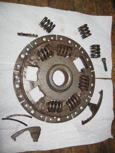
For those who don’t know, the damper is a disk device with about a half a dozen springs used to dampen the shock being transmitted from the engine to the transmission. It looks similar to a clutch plate on a car without the throw-out bearing. The disk is bolted to the flywheel and the transmission shaft is connected to the disk through a spline. These two pieces are connected to each other using the springs, which are about 1” in diameter and about 2” long. As these are continually transferring the power from the engine to the transmission, they are always being worked. Over time, they will start to wear the plate and themselves, and start to break into pieces and eventually fall out. If this happens, the worst case is no power being transmitted to the transmission. You may think the transmission is broken, but it is not. Also, pieces of the springs can get lodged behind the flywheel and lock up your engine. Also check this out if you believe you have a locked up engine.
The symptom of wear and possible failure is noise coming from the transmission while running at low RPM’s. It has been described as marbles running around in an empty coffee can or stones in a hubcap.
Since I knew my damper was worn, having seen it three years ago while having a rebuild done on the engine, I knew it would need replacement eventually. Since I now had the telltale noise, I decided to do it this fall after haul out. I also used this time to replace the cutless bearing and check the drive shaft for trueness.
The first thing I needed to do was pull the shaft to have room to slide the transmission back. Since I have a single, the propeller is protected by a rudder that is mounted on a skeg. I pulled the prop and thought I could push the rudder to the side enough to pull the shaft out after unbolting the bottom rudder bearing from the skeg. No such luck. Since I am on hard gravel, I dug a small trench about 12” deep and 3” wide perpendicular to the keel. I had enough clearance to drop the rudder in the trench and remove it completely from the boat. Pulling the shaft (‘s) was interesting. There are two sections, each about 10’ long. These are supported along their length with two pillow block bearings. These were difficult to remove but with a liberal application of Kroil and a wooden mallet, I was able to pull these out. I used a Sawsall to cut out the cutless bearing. I’ll take these to a shop to have them checked for run-out.
The Perkins 6-354 is supported at the front by two engine mounts bolted to the block and at the rear by two mounts bolted to the bell housing. The transmission is then bolted to the bell housing and does not have any of its own mounts. This is interesting since the bell housing must be removed. The easiest way for me was to support the rear of the engine using a small hydraulic bottle jack. This was positioned under the engine so it would come in to contact with the rear edge of the block. This is not very wide and must be done carefully since the oil pan is aluminum. If you don’t do it correctly, I would expect the jack would go right through the pan.
I disconnected the two wires from the transmission switch on the right side which is used to be sure the transmission is neutral prior to starting. I removed the transmission shift cable and the two hydraulic hoses that run from the transmission to the cooler. I disconnected them at the cooler since all the oil had already drained back into the transmission. I covered all the fittings with plastic wrap to keep them clean. You also need to pull the starter off. I marked the position of the two mounts and unbolted them, then removed the bolts holding the bell housing on to the engine. When you do this you will find that two bolts are run from the engine side into the bell housing at the bottom of the engine. There are about a dozen bolts in all. When this is done, check to be sure the jack is just high enough to support the engine but not lift the transmission off its mounts. Now, just simply pull the transmission back about 6”, it will slide easily. The transmission and bell housing are balanced enough that it will not tip over on you. You may want to put a block of wood under it to support it for safety. My damper was 13” in diameter with the 6 bolt holes, 6” apart and 6” from the center. The disk was well worn, 3 springs had their last coil broken off and they were laying in the bell housing. American Diesel sold me a universal unit that has various bolt patterns to match different flywheels. I used a thread locking compound and bolted the new damper in place.
Now came, for me, the difficult part, sliding the transmission shaft into the damper spline. You need to be exactly lined up to get this to fit properly. After a few tries, I got the surfaces within a ½” with an easy slide. I was in! Now it was just a matter of bolting everything up and re-attaching all the hoses and wires. I was careful in lining up the mounts to make sure they were exactly where they were originally.
Total time - Removal: 3 hours, which included a lot of time understanding the layout and position of all the parts. Installation: 2 hours, which included the false starts in aligning the transmission to the engine.
Terry Hoy
# 1597
Meridian
Wittholz 40
Kalamazoo, MI
--------------------------------------------------------------
Having just done this, I wanted to share the information with the List. While the work done here was with a Perkins 6-354 and a Borg Warner Velvet Drive transmission, it may be similar to other engine/transmission combinations.
For those who don’t know, the damper is a disk device with about a half a dozen springs used to dampen the shock being transmitted from the engine to the transmission. It looks similar to a clutch plate on a car without the throw-out bearing. The disk is bolted to the flywheel and the transmission shaft is connected to the disk through a spline. These two pieces are connected to each other using the springs, which are about 1” in diameter and about 2” long. As these are continually transferring the power from the engine to the transmission, they are always being worked. Over time, they will start to wear the plate and themselves, and start to break into pieces and eventually fall out. If this happens, the worst case is no power being transmitted to the transmission. You may think the transmission is broken, but it is not. Also, pieces of the springs can get lodged behind the flywheel and lock up your engine. Also check this out if you believe you have a locked up engine.
The symptom of wear and possible failure is noise coming from the transmission while running at low RPM’s. It has been described as marbles running around in an empty coffee can or stones in a hubcap.
Since I knew my damper was worn, having seen it three years ago while having a rebuild done on the engine, I knew it would need replacement eventually. Since I now had the telltale noise, I decided to do it this fall after haul out. I also used this time to replace the cutless bearing and check the drive shaft for trueness.
The first thing I needed to do was pull the shaft to have room to slide the transmission back. Since I have a single, the propeller is protected by a rudder that is mounted on a skeg. I pulled the prop and thought I could push the rudder to the side enough to pull the shaft out after unbolting the bottom rudder bearing from the skeg. No such luck. Since I am on hard gravel, I dug a small trench about 12” deep and 3” wide perpendicular to the keel. I had enough clearance to drop the rudder in the trench and remove it completely from the boat. Pulling the shaft (‘s) was interesting. There are two sections, each about 10’ long. These are supported along their length with two pillow block bearings. These were difficult to remove but with a liberal application of Kroil and a wooden mallet, I was able to pull these out. I used a Sawsall to cut out the cutless bearing. I’ll take these to a shop to have them checked for run-out.
The Perkins 6-354 is supported at the front by two engine mounts bolted to the block and at the rear by two mounts bolted to the bell housing. The transmission is then bolted to the bell housing and does not have any of its own mounts. This is interesting since the bell housing must be removed. The easiest way for me was to support the rear of the engine using a small hydraulic bottle jack. This was positioned under the engine so it would come in to contact with the rear edge of the block. This is not very wide and must be done carefully since the oil pan is aluminum. If you don’t do it correctly, I would expect the jack would go right through the pan.
I disconnected the two wires from the transmission switch on the right side which is used to be sure the transmission is neutral prior to starting. I removed the transmission shift cable and the two hydraulic hoses that run from the transmission to the cooler. I disconnected them at the cooler since all the oil had already drained back into the transmission. I covered all the fittings with plastic wrap to keep them clean. You also need to pull the starter off. I marked the position of the two mounts and unbolted them, then removed the bolts holding the bell housing on to the engine. When you do this you will find that two bolts are run from the engine side into the bell housing at the bottom of the engine. There are about a dozen bolts in all. When this is done, check to be sure the jack is just high enough to support the engine but not lift the transmission off its mounts. Now, just simply pull the transmission back about 6”, it will slide easily. The transmission and bell housing are balanced enough that it will not tip over on you. You may want to put a block of wood under it to support it for safety. My damper was 13” in diameter with the 6 bolt holes, 6” apart and 6” from the center. The disk was well worn, 3 springs had their last coil broken off and they were laying in the bell housing. American Diesel sold me a universal unit that has various bolt patterns to match different flywheels. I used a thread locking compound and bolted the new damper in place.
Now came, for me, the difficult part, sliding the transmission shaft into the damper spline. You need to be exactly lined up to get this to fit properly. After a few tries, I got the surfaces within a ½” with an easy slide. I was in! Now it was just a matter of bolting everything up and re-attaching all the hoses and wires. I was careful in lining up the mounts to make sure they were exactly where they were originally.
Total time - Removal: 3 hours, which included a lot of time understanding the layout and position of all the parts. Installation: 2 hours, which included the false starts in aligning the transmission to the engine.
Terry Hoy
# 1597
Meridian
Wittholz 40
Kalamazoo, MI