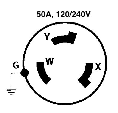
Okay, a little more info. The 50 amp pedestals in the marina are three conductor plugs. One neutral/ground, and two 115v hots, measured with a multimeter. Across the two hots is 230v measured.
At the last slip,LeoKa was plugged into a 50 amp pedestal, labeled "50amp 125/250v"
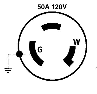
He was using an adapter which used three conductors, the TO three conductors, but was labeled 50amp 125v at the end that plugged into the pedestal, and 50 amp 125v at the other end. The three conductors were neutral/ground, and 125v, 125v, but measuring across the two 125v conductors yielded O volts, so apparently the two conductors are of the same phase, with one of the 125v wires terminating within the adapter pigtail. So we extrapolate that the boat is wired 50 amp, 125v ONLY.
The above info is confirmed by testing.
Now for the extrapolation. . . . I would THINK (but would have to be verified by testing) that the outputs from two adjacent pedestals would be of the same phase . . . . but they may NOT be, (again, must test) if they ARE, then using a reverse adapter at the boat end, it should be possible to plug in two extension cords to the two male inputs of the reverse adapter on the boat, and being of the same phase, it should provide the same 125v, but at 60 amps to the boat (limited to 50 amps by the panel circuit breaker on the boat). If they are of opposing phases, it obviously won't work.
With me so far? Nope Any holes in our thinking? Seriously, if we're misinterpreting this, please chime in here!