GregBrannon
Guru
Our Galley Maid BBHW vertical windlass froze up our first trip out this season. In the heat of the moment while raising the chain rode and anchor by hand on a hot, humid morning, I told the admiral, "Never let me do this again." She took the comment literally (silly woman) and wouldn't let us go out until a solution was found.
I priced replacements and consulted Rick at Galley Maid. Rick is an excellent resource, knows the product extremely well, will provide any assistance he can over the phone, and rebuilds/repairs windlasses sent to Galley Maid in Florida. If someone nearby needs help in person, Rick does that on weekends. Since the windlass is described as one of those 'bullet-proof' models with parts readily available and Rick's help at hand, I decided to rebuild rather than replace. As evidence of its durability, I'm sure that most of the windlass' parts have been on the boat for nearly 40 years with hard use by the PO. Other parts had been replaced within the last 10 years.
Starting below deck, the major component are motor, gear box, spur gear (in the gear box, pressed onto the output shaft), output shaft, gear box top (a cast aluminum frame that includes the mechanical interface to the bottom of the deck and the 'tube' through which the output shaft passes through the deck), and the deck plate. The above-deck components include the typical parts for raising chain and/or rope and the friction mechanism for controlling how freely those parts spin on the shaft. Those components were not replaced during this rebuild.
Here are a few pictures for context. First, the before below deck assembly with the motor and gear box removed. I troubleshot the motor first, testing it and the mechanicals separately. The motor was strong - stand back when energizing it! - and the voltage when under load was acceptable, but the mechanicals were frozen solid.

In the first picture which is upside down, note the spacers between the top of gear box top and the deck. Those spacers are 3/4". The spacers control the height of the above-deck assembly above the deck plate. In the second picture, the clutch plate is still on the output shaft, because the thing was a bugger to remove, requiring many smacks with a hammer to bend back the flange next to the output shaft that had formed over years of use, holding the plate to the output shaft. The hammering was done per Rick's direction.
We (the admiral helped) removed the entire remaining assembly by banging the heck out of a pipe and end cap taller than the output shaft and less diameter than the deck plate hole with a 10-pound sledge. (Rick's method.) The admiral bravely held the pipe with hearing protection while I hit the pipe with the sledge. I was afraid of missing the pipe completely, injuring the admiral or finding a weakness in the boat and splintering fiberglass, so I started off weakly. As I gained confidence in my aim, the force of the swing increased. I didn't count, but I figure it took 15-20 whacks to free the tube from where it was pressed into the deck plate. A nut that was easy to reach was left loosely threaded onto one of the through-deck bolts that hold the gear box cover to the deck so that the assembly wouldn't go crashing into the anchor locker when it came free. In the process of disassembly, we discovered that 2 of those 6 through-deck SS bolts were severely cracked and corroded, one probably already broken before disassembly. I replaced all 6 of them.
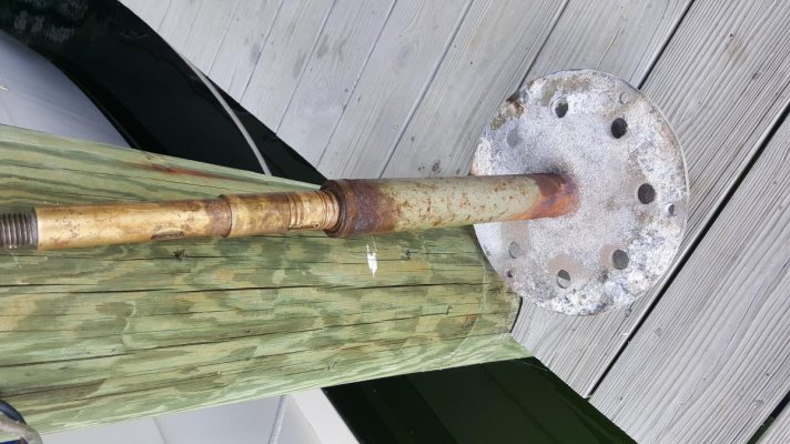
The third picture shows the entire assembly after removal, and the last shows the bottom of the assembly with the spur gear removed. I removed the spur gear with a gear puller before sledging the whole thing out of the boat. The spur gear has 2 holes for set screws. When I called Rick concerned that I couldn't get the spur gear off, he told me that he often adds a double set screw to one of the holes to prevent the set screw backing out, allowing the spur gear to slip off the output shaft.
Note the corrosion at the bottom of the tube through which the output shaft passes. The moisture that causes that corrosion and the resulting fragments of corroded material end up in the gear box. My gear box was relatively clean with no corrosion or damage to the gears that I could see, so I suspect that both the gear box and the electric motor were replaced within the last ~10 years. Galley Maid made a design change that added an O-ring and washer above the bushing at the top of the shaft tube to prevent moisture intrusion.
Because the shaft was frozen to the bushing inside the tube and I didn't have the tools to free it, I took the whole assembly plus the spur gear to a machine shop to press out the shaft and bushing, assess which parts needed to be replaced, and then reassemble for me. I'll show the results of the machine shop's work and the design changes recommended and made in my next post.
I priced replacements and consulted Rick at Galley Maid. Rick is an excellent resource, knows the product extremely well, will provide any assistance he can over the phone, and rebuilds/repairs windlasses sent to Galley Maid in Florida. If someone nearby needs help in person, Rick does that on weekends. Since the windlass is described as one of those 'bullet-proof' models with parts readily available and Rick's help at hand, I decided to rebuild rather than replace. As evidence of its durability, I'm sure that most of the windlass' parts have been on the boat for nearly 40 years with hard use by the PO. Other parts had been replaced within the last 10 years.
Starting below deck, the major component are motor, gear box, spur gear (in the gear box, pressed onto the output shaft), output shaft, gear box top (a cast aluminum frame that includes the mechanical interface to the bottom of the deck and the 'tube' through which the output shaft passes through the deck), and the deck plate. The above-deck components include the typical parts for raising chain and/or rope and the friction mechanism for controlling how freely those parts spin on the shaft. Those components were not replaced during this rebuild.
Here are a few pictures for context. First, the before below deck assembly with the motor and gear box removed. I troubleshot the motor first, testing it and the mechanicals separately. The motor was strong - stand back when energizing it! - and the voltage when under load was acceptable, but the mechanicals were frozen solid.
In the first picture which is upside down, note the spacers between the top of gear box top and the deck. Those spacers are 3/4". The spacers control the height of the above-deck assembly above the deck plate. In the second picture, the clutch plate is still on the output shaft, because the thing was a bugger to remove, requiring many smacks with a hammer to bend back the flange next to the output shaft that had formed over years of use, holding the plate to the output shaft. The hammering was done per Rick's direction.
We (the admiral helped) removed the entire remaining assembly by banging the heck out of a pipe and end cap taller than the output shaft and less diameter than the deck plate hole with a 10-pound sledge. (Rick's method.) The admiral bravely held the pipe with hearing protection while I hit the pipe with the sledge. I was afraid of missing the pipe completely, injuring the admiral or finding a weakness in the boat and splintering fiberglass, so I started off weakly. As I gained confidence in my aim, the force of the swing increased. I didn't count, but I figure it took 15-20 whacks to free the tube from where it was pressed into the deck plate. A nut that was easy to reach was left loosely threaded onto one of the through-deck bolts that hold the gear box cover to the deck so that the assembly wouldn't go crashing into the anchor locker when it came free. In the process of disassembly, we discovered that 2 of those 6 through-deck SS bolts were severely cracked and corroded, one probably already broken before disassembly. I replaced all 6 of them.
The third picture shows the entire assembly after removal, and the last shows the bottom of the assembly with the spur gear removed. I removed the spur gear with a gear puller before sledging the whole thing out of the boat. The spur gear has 2 holes for set screws. When I called Rick concerned that I couldn't get the spur gear off, he told me that he often adds a double set screw to one of the holes to prevent the set screw backing out, allowing the spur gear to slip off the output shaft.
Note the corrosion at the bottom of the tube through which the output shaft passes. The moisture that causes that corrosion and the resulting fragments of corroded material end up in the gear box. My gear box was relatively clean with no corrosion or damage to the gears that I could see, so I suspect that both the gear box and the electric motor were replaced within the last ~10 years. Galley Maid made a design change that added an O-ring and washer above the bushing at the top of the shaft tube to prevent moisture intrusion.
Because the shaft was frozen to the bushing inside the tube and I didn't have the tools to free it, I took the whole assembly plus the spur gear to a machine shop to press out the shaft and bushing, assess which parts needed to be replaced, and then reassemble for me. I'll show the results of the machine shop's work and the design changes recommended and made in my next post.