Engine Alignment Comments Appreciated

The friendliest place on the web for anyone who enjoys boating.
If you have answers, please help by responding to the unanswered posts.

Oil Gypsy

Veteran Member
Joined
Sep 25, 2019
Messages
55
Location
Canada
Vessel Name
Dauntless
Vessel Make
Grand Banks 36 Classic #248
So……

We have two Ford Lehmans with AS7-71C transmissions. The starboard transmission developed a leak at the oil seal, Ive replaced the seal but in doing so opened another can of worms.

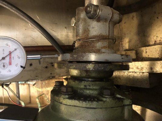
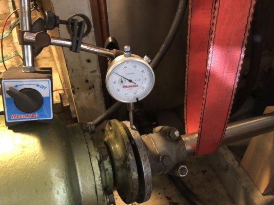
When I disconnected the shaft the coupling was at the top of the vertical movement range of the shaft, to reconnect the coupling I had to really heave on it. I put a dial gauge on the shaft coupling and it had a range of about 0.35” from resting bottom to fully lifted without straining, to reconnect the coupling I had to lift it more to about 0.4”.

When we bought the boat we were told the mounts had recently been changed, it would appear that the alignment was poorly done, if at all.

Ive made a temporary support for the shaft and adjusted it so that its at the mid point of the vertical movement range, 0.17”

Now by sight the back of the engine needs to go down about 0.2” and the front even more to make the shaft coupling and transmission output connection parallel.

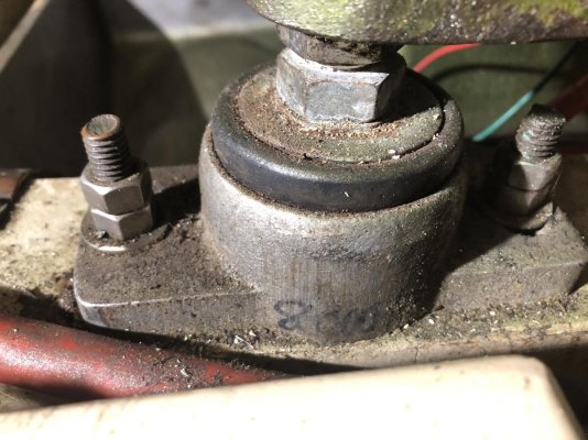
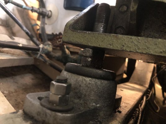
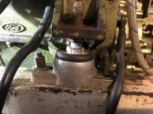
This is where the problems start, the mounts at the front of the engine are almost bottomed out, maybe one thread remaining, certainly not enough to line up the engine properly.

I believe the only options are to either change the mounts or lift the engine and recess the mounts into the engine bearers (these are 3” wide and 12” deep).

If anyone has any experience or better ways of resolving the issue I would really appreciate your input.

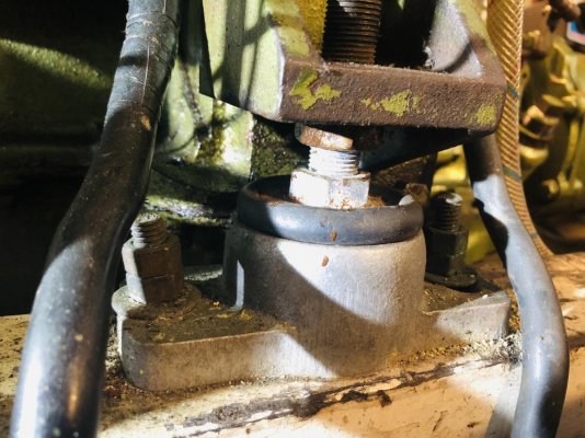
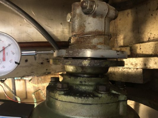
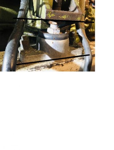
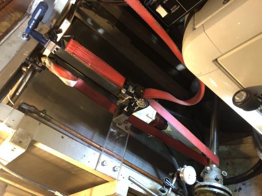
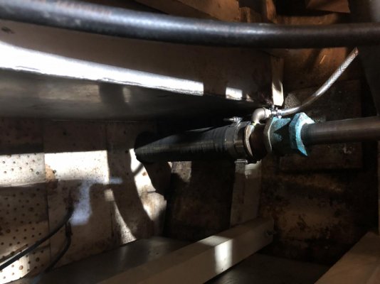
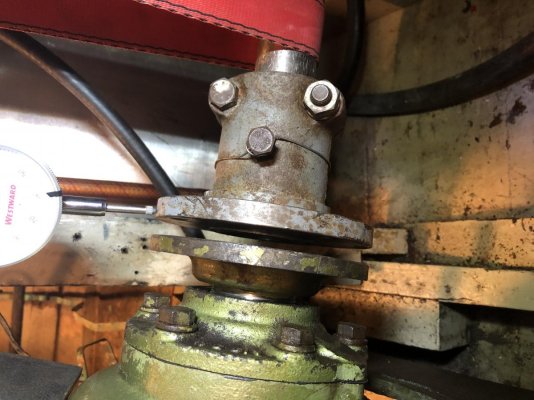
The photos show the front engine mounts which are almost bottomed out, the rear engine mount which has about a 1/4” range until it bottoms out and the coupling/connector with the shaft supported at the mid point of the vertical range.
 

Attachments

  • IMG_5810.jpg
    IMG_5810.jpg
    152.9 KB · Views: 59
  • IMG_5804.jpg
    IMG_5804.jpg
    118.1 KB · Views: 54
  • IMG_5809.jpg
    IMG_5809.jpg
    104 KB · Views: 51
  • IMG_5817.jpg
    IMG_5817.jpg
    166.9 KB · Views: 64
  • IMG_5805.jpg
    IMG_5805.jpg
    111.9 KB · Views: 47
When you spin the shaft now is it true? Or does it have runout on the coupling?
 
Ive turned the shaft through a couple of revolutions with the support in place and it indicates 0.015” at the coupling. I haven't measured at the shaft.
 
If there is room at each forward engine mounts I would use hat shaped 1/2 inch thick x 3 inch wide bar with engine mounts on each side. The bar would be bolted to the engine mount and the rubber mounts would be on each side. The two mount system would require a softer mount due to two mounts supporting each engine mounting bracket. I would not modify the engine beds. The hat bracket.would allow you to lower the engine front an inch or more depending on the leg length of the hat section.
Also you could use a half nut on the to pick up some more room on the existing rubber mount. The coupling should freely slide together without forcing. The flanges of the couling should be less than 0.003 inches using feeler gauges. Rotate the shaft and verify the clearance remains the same. New mounts will settle some so you should check after 5 to 10 hours run time and in the 100 hr range.
 
Is the boat in or out of the water?
Also you mentioned supporting the shaft while turning, why?
 
You should take some of the shaft droop out to simulate it being hooked up to the transmission.
 
You should take some of the shaft droop out to simulate it being hooked up to the transmission.

How was it determined there was droop? Most I have seen have a 1-2 foot shaft from stuffing box. I doubt that would droop.
 
There pretty much always is droop if the shaft is unhooked. It is usually a very heavy piece of metal.
 
In an old cat diesel manual the method to address shaft droop required a few calculations. First was determining the shaft length from the last shaft support to the transmission coupling and measuring the coupling sufficiently to allow calculating the volume. Steel and stainless steel weights about 0.28 lbs per inch cubed. Using 1/2 the shaft weight plus the coupling gives you the weight that using a spring scale you would pull upward on the shaft coupling when they fit together. The engine & transmision would be adjusted/aligned so come together with no interference. This process would eliminate the shaft droop. It becomes important if there is a significant distance transmission flange and the shaft support.
 
In an old cat diesel manual the method to address shaft droop required a few calculations. First was determining the shaft length from the last shaft support to the transmission coupling and measuring the coupling sufficiently to allow calculating the volume. Steel and stainless steel weights about 0.28 lbs per inch cubed. Using 1/2 the shaft weight plus the coupling gives you the weight that using a spring scale you would pull upward on the shaft coupling when they fit together. The engine & transmision would be adjusted/aligned so come together with no interference. This process would eliminate the shaft droop. It becomes important if there is a significant distance transmission flange and the shaft support.

Exactly.
 
Don't trust me on this. See what others think, but...

I don't know that you need that double nut at the bottom as long as you have a double nut at the top.

Going from a double nut underneath to a single nut underneath would give you more downward adjustment.

Then, on top you'd put on one nut and crank it down, and then put another nut on top of it to lock everything in place.

I'm not where I can look at how mine are done now, but I know I've seen installations with only one nut underneath.

When mine were replaced, the engine wasn't lifted. The mount to be replaced and it's partner (other front or other back) was loosened and a hydraulic strong arm from harbor freight was used to suppory the side being replaced. Maybe it was lifted a hair, but just enough to pull it out and slide the replacement in. Then everything was sat back down and aligned.

In my case I had more adjustment underneath which enabled the bottom nut to be backed down and the mount to be pushed up to help get it out and then replacement in. In your case you might need to lift a bit more, but you might be able to get away without an A-frame, etc.

Good luck!
 
Last edited:
You know this. The rule of thumb on new mounts is to let them "settle" after installation at least 24 hrs before final in the water alignment. It is recommended to check again in 6 months because the rubber continues to settle. After 6 months "creep" is mostly done and will typically not be an issue. This 6 month "post initial creep" may be what you are dealing with.

About the adjustment being bottomed out, I'm with STB, and maybe throw a few washers in so the nut stays put bottomed out, OR, thin that nut down a few thousandths on the grinder.

It may be the photo angle, and this may not be an issue at all. Mounts like to be loaded "square," they don't work as designed if loaded unevenly. This may also stress the stud. A little is acceptable. This may also decrease lifespan. Shims to even the load are the typical way to square up the loading.

$0.02 :socool:
 

Attachments

  • mount load angle.jpg
    mount load angle.jpg
    58.7 KB · Views: 44
I have a 135 and my mounts are different. Previous yard had put spacers under my mounts, removing them gave me 3/8".

Also as your motor goes forward you get more height. 1" does wonders if you have clearance.

The mounts will settle significantly. Expect it. Just keep at it and the flange will line up and moving the engine around will become easier.

Check out my blog where I did mine, grandbankschoices.
 
I had a Ford Lehman on my previous boat and went through the same exercise. I agree with your general approach of finding the mid-point of the shaft "slop". You also need to do this in the side-to-side direction.

My concern is: how did the boat get into this situation? Has it always been forcing the shaft up against its inboard bearing? Has something changed ? (bent shaft, hard grounding?). Mounts tend to sag with age, but in your case the mounts are too high.

I assume that the boat is in the water - this is important for the final alignment.
 
If the shaft was not centered properly then you could have wear on the shaft log and cutlass bearings. Ask me how I know. A previous boat was way out of alignment when I bought it. Had to put a new shaft log in it on both engines.
 
Went back to the boat today with a fresh head and changed my set up a bit, I was supporting the shaft with a block of wood with a 1.5” half circle cut out for the shaft. Ive now changed it to a ratchet strap hanging from a clamp secured to a cabin deck beam. This gives much finer control while lifting the shaft onto the mid vertical position. I then checked the vertical movement again, I did it several times and the average upward movement was 0.65”. Using the ratchet strap I lifted the shaft to the midpoint.

The position of the coupling when compared to the transmission was still out of alignment with the engine high but not nearly as bad.

I saw the comments regarding shaft droop and I did calculate this before, it works out to about 22lbs, but on the GB36 its complicated by the fact that the stuffing box isn't secured to the boat, its in a 3” heavy duty hose which is about 3ft - 4ft from the hull shaft opening and the last cutlass bearing (there are 3 on each shaft). There should be an extra allowance for the weight of the stuffing box and the hose, but Im not sure how to calculate this. Which is why I chose the mid point method which Ive seen mentioned on the forum several times. But just to be sure I have ordered an digital scale from Amazon which I will check the upward tension Im putting on the shaft.

Regarding the alignment of the engine mount (Keys Disease) that was an error induced by the camera angle, the engine foot is parallel to the engine bed.

And yes, the boat is in the water.

Anyway thanks for the comments, reading them helps me think the problems through.
 

Attachments

  • IMG_5819.jpg
    IMG_5819.jpg
    175.6 KB · Views: 38
  • IMG_5823.jpg
    IMG_5823.jpg
    117.6 KB · Views: 38
  • IMG_5825.jpg
    IMG_5825.jpg
    128.3 KB · Views: 38
  • IMG_5822.jpg
    IMG_5822.jpg
    85.4 KB · Views: 39
  • IMG_5826.jpg
    IMG_5826.jpg
    137.4 KB · Views: 37
Single nut the bottom and double the top and you will be fine.
 
There pretty much always is droop if the shaft is unhooked. It is usually a very heavy piece of metal.

The stuffing box or shaft seal usually does not support the shaft at all. Behind that is the stern tube which shouldn't be touching the shaft at all. Behind that is the intermediate (or only) strut bearing and that could be several feet further aft. The strut bearing(s) is/are the only things that support the shaft. That's a lot more unsupported shaft than the foot or two you can see, could be 6 feet or more. When you uncouple it's going to drop until it hits the stern tube, that could be an inch or more at the coupling.
 
Back
Top Bottom